Exploring the New Analyzer Tab: Map View, Image Manager, and Reconstruction Controls
The Analyzer tab has been updated with a new Map view mode and additional controls for reviewing imagery, camera positions, reconstruction data, and reference points. The existing Classic view remains available and works the same way as before, while the new Map view provides a more spatially intuitive way to inspect, review, and edit your project.
Watch the Analyzer Tab Tutorial
Walkthrough of the new Map view, Image Manager, and reconstruction controls
Classic and Map Views
At the top left of the Analyzer, you can switch between the available viewing modes. Classic view provides the familiar Analyzer workspace, displaying project imagery and reconstruction information as it has in previous versions of the app.
The new Map view displays image previews and camera positions directly over a basemap. This makes it easier to understand where imagery was captured, visualize flight coverage, and inspect the spatial relationship between images and the project area.
Image Manager
Map view also introduces a new Image Manager button on the left side of the workspace, providing access to project imagery for reviewing and managing individual images within the dataset. Expand the compact Image Manager panel using the arrow on its right side to reveal the image information table. Use the search control to find a specific image, or click a column heading to sort the list. For RTK imagery, status badges such as Fixed help identify the positioning solution associated with each image.
From here, you can review and edit the positional accuracy information for individual images, including the X, Y, and Z coordinates representing Easting, Northing, and Height. You can also review and edit the orientation accuracy information, including roll, pitch, yaw, or omega, phi, kappa, and edit their uncertainty values as well.
Adjustment information is also displayed for each image, including X, Y, and Z error, which shows the difference between the original camera position and its adjusted position in the photogrammetric solution. Reprojection Error provides an additional measure of how well image observations align with the reconstructed solution. You can also switch between Position and Orientation information to review additional camera data associated with each image.
To make changes, enter Edit mode using the pencil button. In this mode, the table displays (sigma) σX, σY, and σZ fields for camera-position uncertainty. These uncertainty values are different from the (delta) ΔX, ΔY, and ΔZ adjustment differences shown in the review table. Use the confirm or cancel controls when you finish editing. For further analysis or recordkeeping, the Image Manager also provides options to download the project images or download a report containing the adjustment data.
Lasso Selection and GCP Images
To select a group of images spatially, use the Lasso selection tool in the Image Manager toolbar. Draw an outline around the image positions you want to select on the map, then use the checkmark to confirm your selection. You can also undo the outline or cancel selection mode. When working with a reference point, the Add Selected Images to GCP control lets you associate selected images with that point for marking and review.
Map Display Controls
Several new controls on the right side of the Map view let you customize how project information is displayed. Marker Mode controls the information shown for the project imagery. You can visualize Flight Lines, RTK Solution (if applicable), or Image Reconstruction information depending on what you want to inspect.
Appearance Mode allows you to view which images capture the specific reference point you have selected. You can change between the visualization to view the tied photos highlighted as Rings or Lines back to the reference point. You can also customize the units used throughout the Analyzer, including General Units, Location Units, Angle Units, and Orientation Units.
Reconstruction Settings
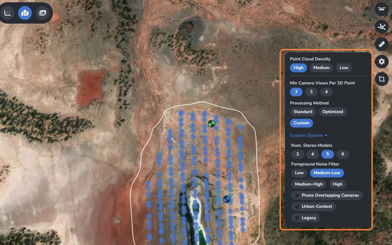
Open Dense Point Cloud Settings on the right side of the Analyzer for additional control over the 3D reconstruction. These settings let you configure point density, camera observation requirements, and custom filtering options to control how image observations are used when generating the dense point cloud.
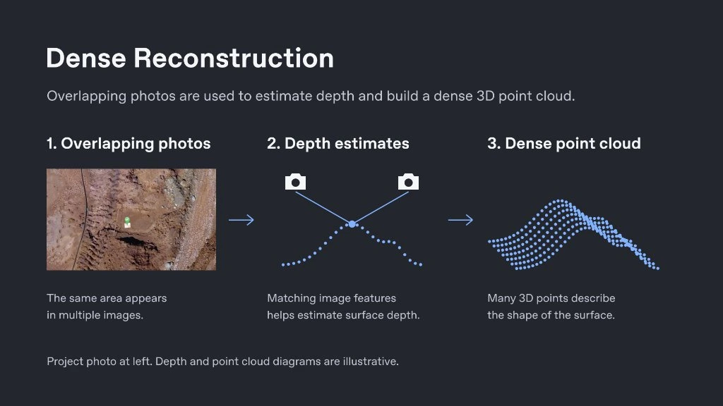
Dense Reconstruction
During dense reconstruction, overlapping photos from across the survey are compared to match image features and estimate surface depth. Those depth estimates are then combined to build a dense 3D point cloud that describes the shape and surface detail of the site.
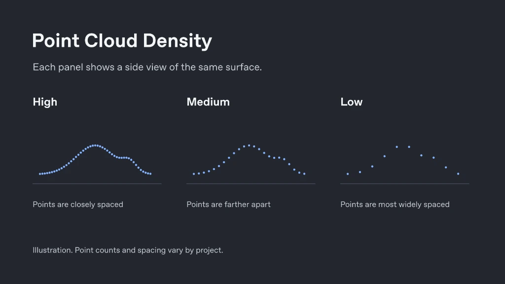
Point Cloud Density
Point Cloud Density can be set to High, Medium, or Low, allowing you to control the density and point spacing of the generated point cloud. Choosing High produces more closely spaced points for fine surface detail, while Medium or Low generates fewer points with wider spacing for faster processing.
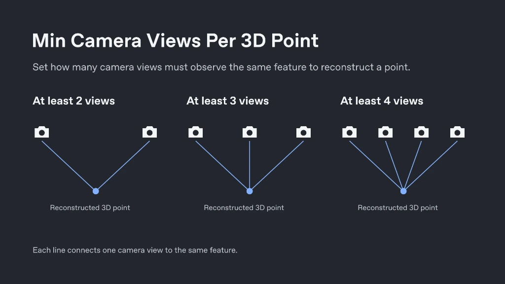
Min Camera Views Per 3D Point
You can set Min Camera Views Per 3D Point to 2, 3, or 4, specifying the minimum number of camera views that must observe the same feature in order to reconstruct each 3D point. Requiring more camera views increases multi-view agreement for reconstructed points, while fewer views can help retain coverage in areas seen by fewer photos.
Processing Method
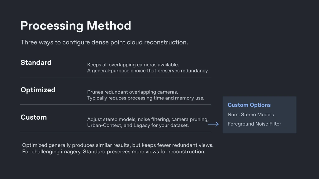
Under Processing Method, you can choose Standard, Optimized, or Custom to configure how the dense point cloud is built. Standard keeps all overlapping cameras available to preserve redundancy, Optimized prunes redundant overlapping cameras to reduce processing time and memory usage, and Custom unlocks advanced controls for stereo models, noise filtering, camera pruning, Urban-Context, and Legacy reconstruction.
Number of Stereo Models
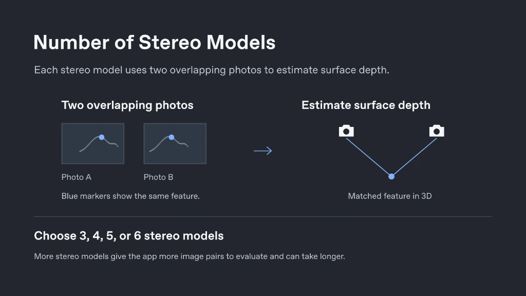
Under Custom Options, you can choose how many stereo models the app uses to estimate depth. A stereo model compares two overlapping photos to work out how far away a surface is. You can choose from three to six stereo models—evaluating more image pairs can improve depth estimation on complex surfaces, though using more models can take longer to process.
Foreground Noise Filter
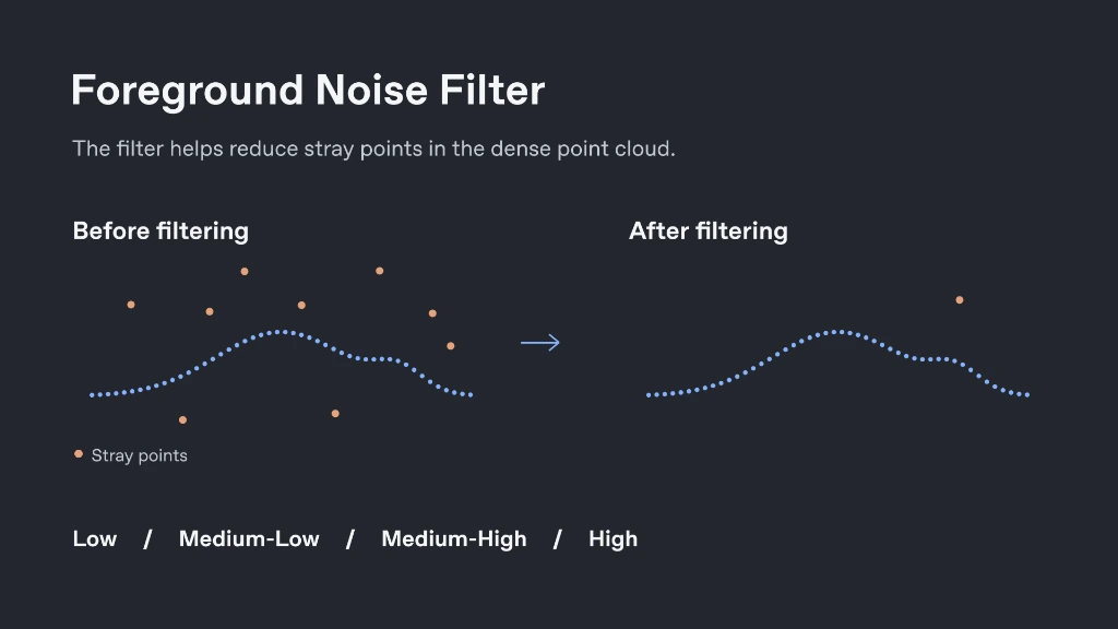
The Foreground Noise Filter helps reduce stray points in the dense point cloud before final deliverables are generated. It offers four filtering levels—Low, Medium-Low, Medium-High, and High—so you can balance stray-point cleanup against surface detail retention for your dataset.
Prune Overlapping Cameras
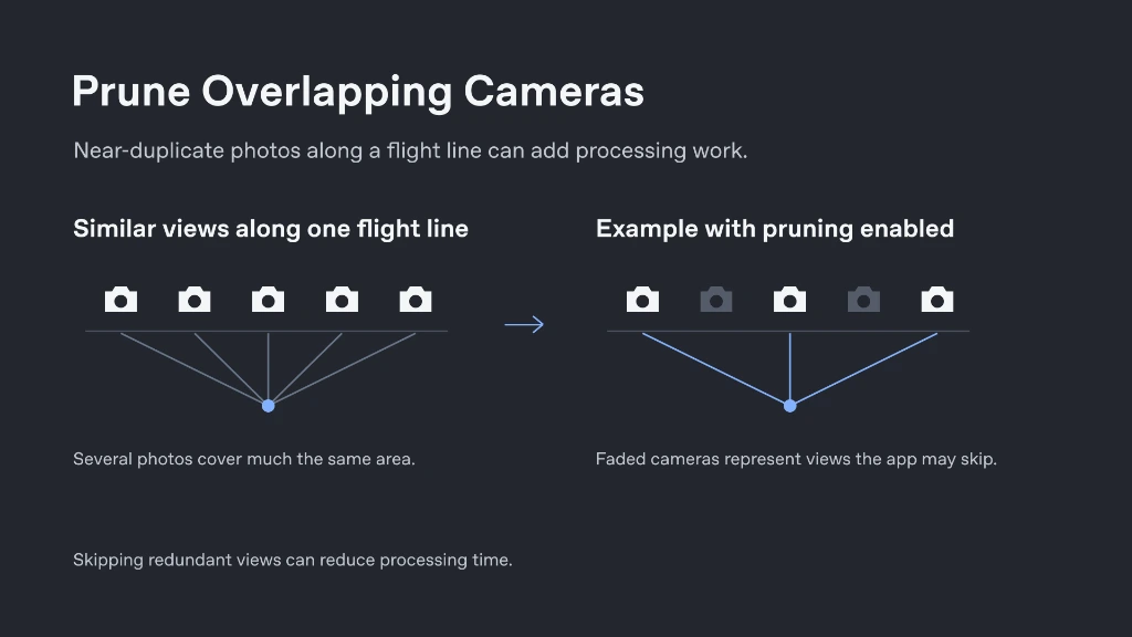
Prune Overlapping Cameras can reduce processing time when many of your photos show the same area from nearly the same angle. For example, if a drone captures several very similar views along a flight line, the app can skip redundant views when building the dense point cloud.
Urban-Context
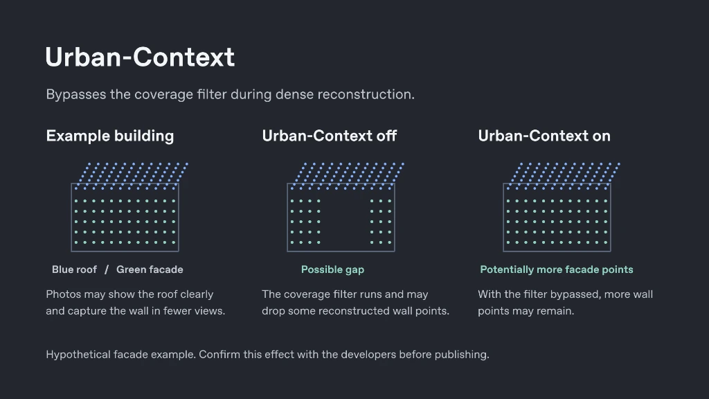
Urban-Context turns off the coverage filter that the app normally applies during dense reconstruction. This changes how the software filters the reconstructed scene, helping retain more points on vertical surfaces and building facades that may appear in fewer views than roofs or ground surfaces.
Legacy
Legacy switches back to the app’s earlier method for building the dense point cloud. Keeping your other settings fixed, you can use Legacy mode to compare how the same dataset and crop area reconstruct with the older and newer point cloud methods.
Clipping Bounds
The Edit Clipping Bounds tool lets you adjust the area of the project included in processing. On the map, the clipping boundary is displayed directly over the project, making it easier to define the area you want to include before processing. Simply draw a polygon of what you would like to keep, and hit the Apply button.
If you need to undo your newly drawn clipping bound, hit Reset to Default Clipping Bounds and hit Apply. You can also reset to your most recent crop. In this tool, you also have the ability to export the clipping bounds, as well as import clipping bounds from a previous project to standardize the covered surface of the site.
Reference Points and GCP Error
Reference points can also be reviewed directly alongside the mapped project imagery, where GCPs are color-coded according to their error to provide a quick visual indication of point quality. Select a GCP to review the images associated with that point in the image strip. Use the Show Error toggle to inspect the reference-point errors, and review the selected point’s (delta) ΔX, ΔY, and ΔZ values for its individual coordinate differences.
Conclusion
Together, these Analyzer updates provide a more visual way to review project imagery, inspect flight and reconstruction information, evaluate reference points, and configure processing before running your project. The original Classic view is still available, while the new Map view adds spatial context and additional controls directly within the Analyzer.