Using the Stereo Reconstruction Tool with PixElement
Exploring the Stereo Reconstruction Tool in PixElement
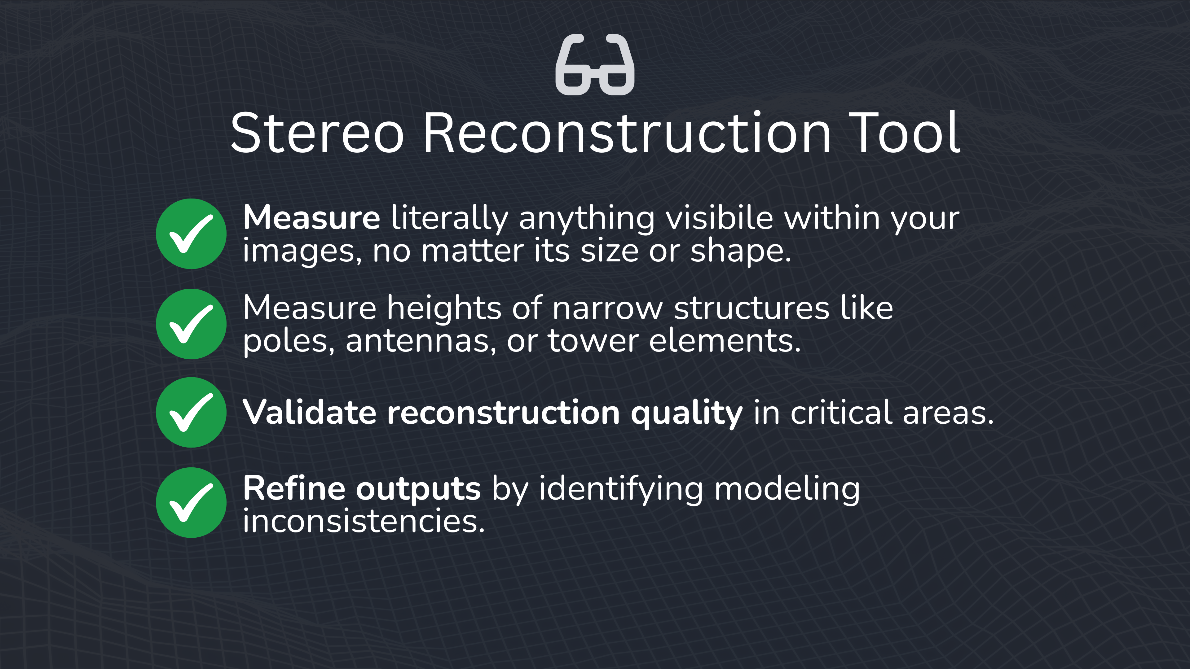
With the Stereo Reconstruction Tool, if you can see a feature in two images, you can measure it, from antennas and light poles, to architectural details and road signs. By comparing overlapping aerial images from different viewpoints the tool calculates parallax to give you accurate height, position, and dimensional data, no matter what automated modeling did or didn’t capture. Please see the video tutorial of this blog post above.
The Stereo Reconstruction Tool allows users to manually select image pairs and inspect scenes from dual perspectives. If a feature is visible in your images, you can measure it, anything from antennas and flagpoles to building edges and road markings. It’s also a powerful tool for:
Getting Started with the Stereo Reconstruction Tool
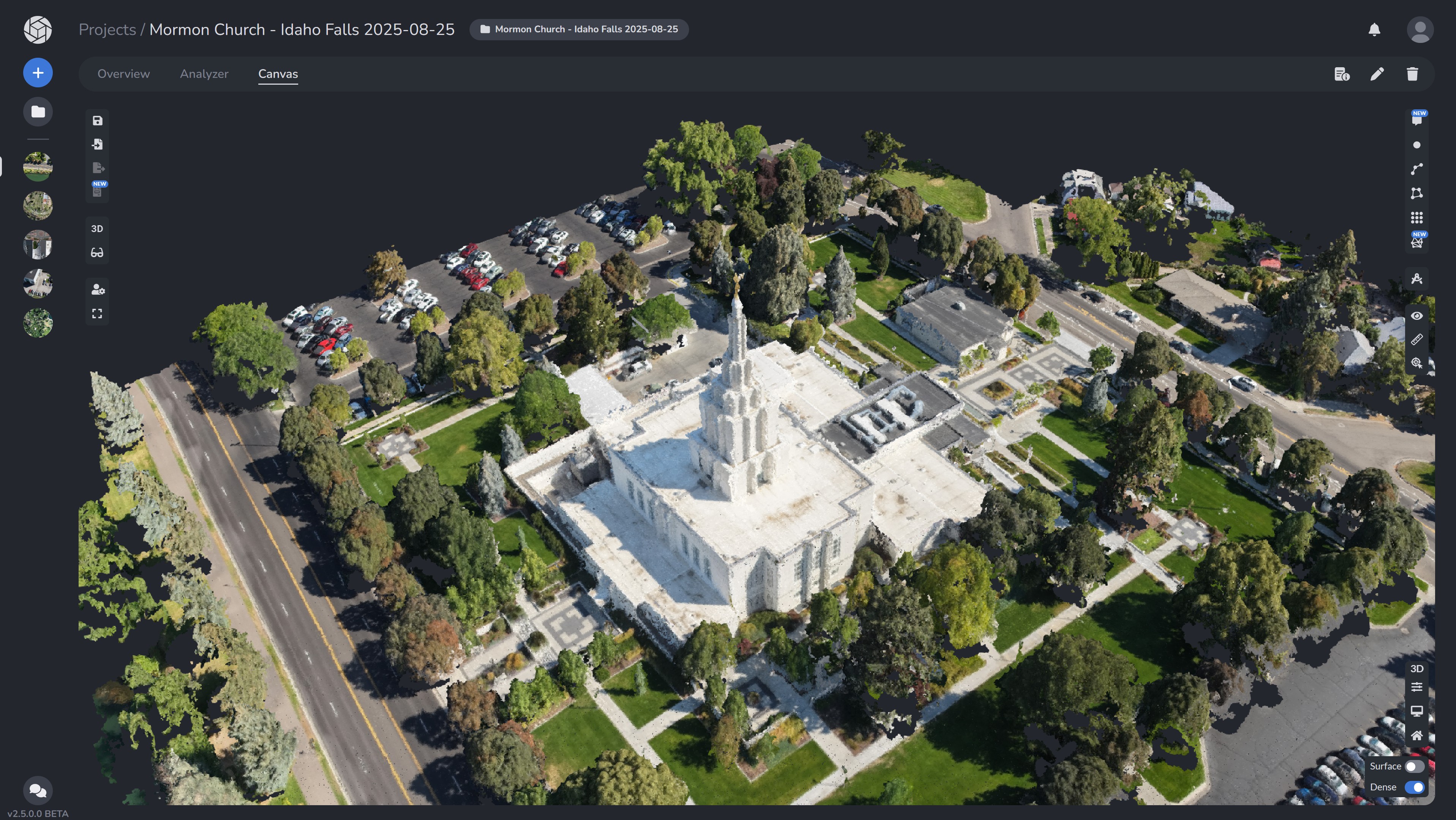
So let’s say for example that you have flown this temple, and need to measure the height of the statue at the top of the building. This would be a good time to use the stereo reconstruction tool to get that exact height.
Starting in the Canvas Tab
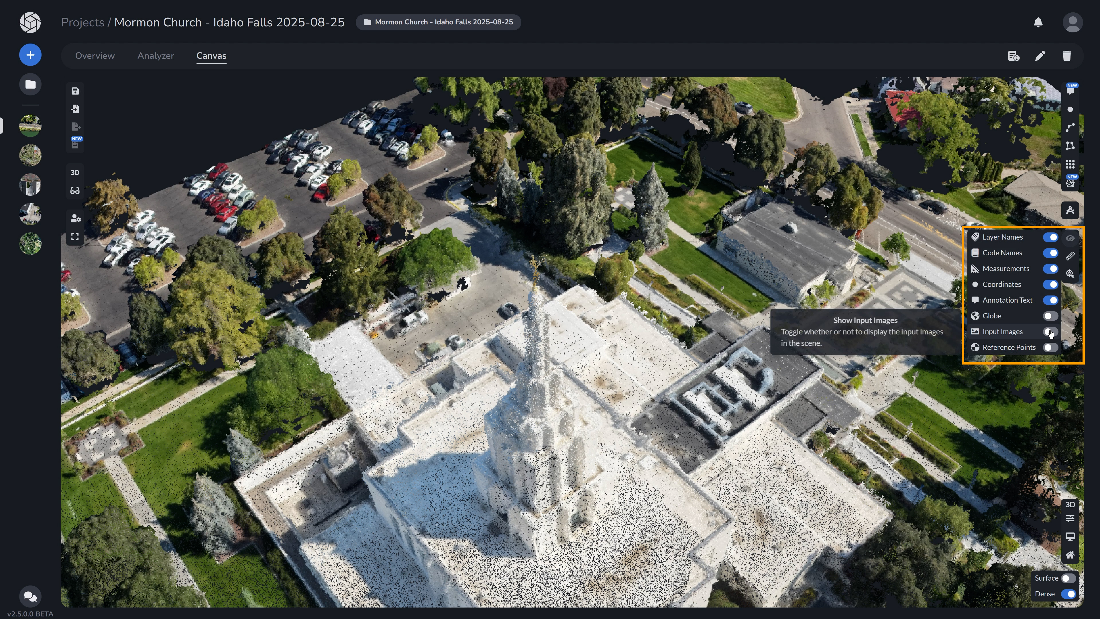
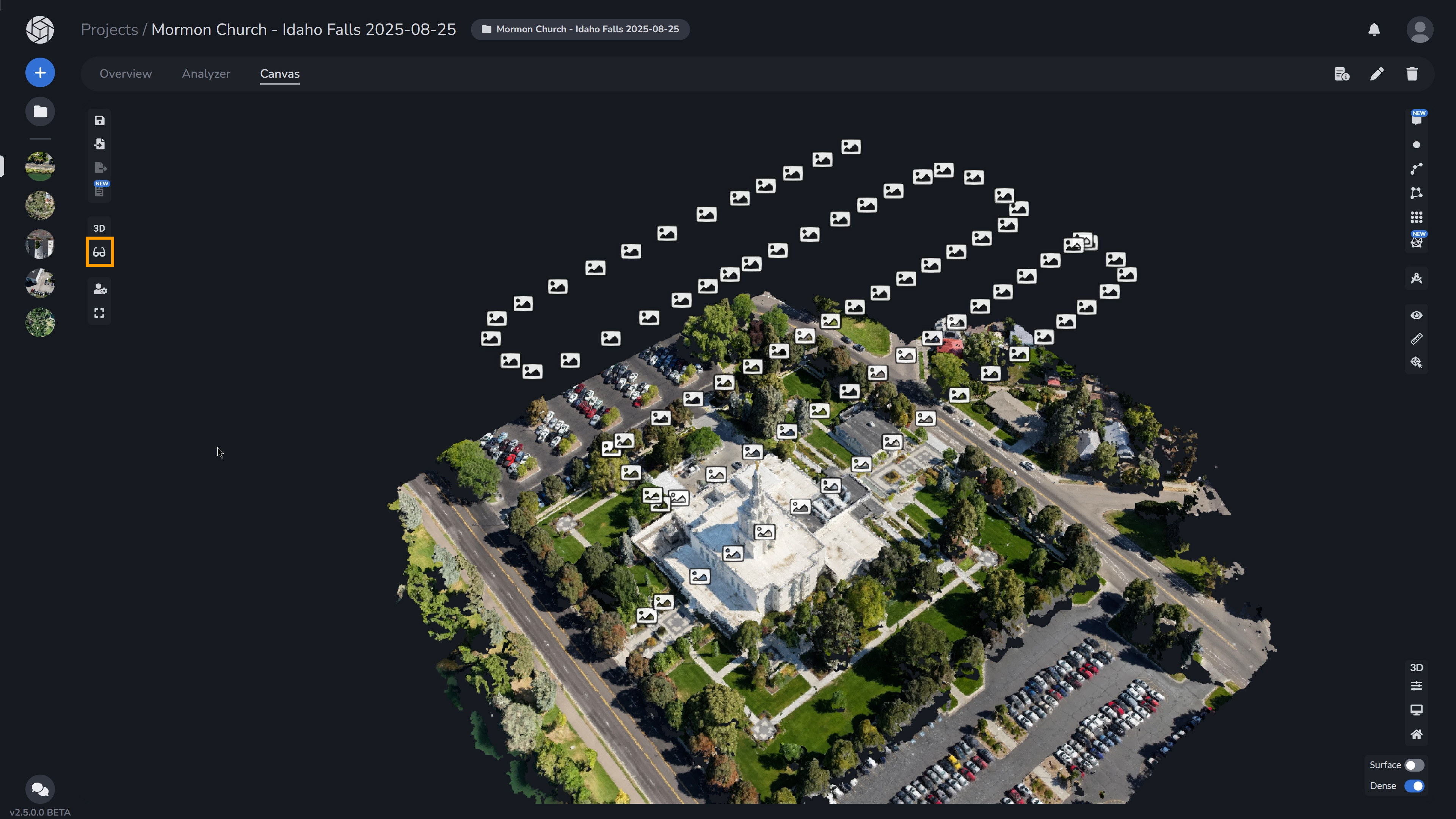
To begin, head over to the “Show” menu in the PixElement Canvas tab. Here, you should enable the input images for stereo reconstruction.
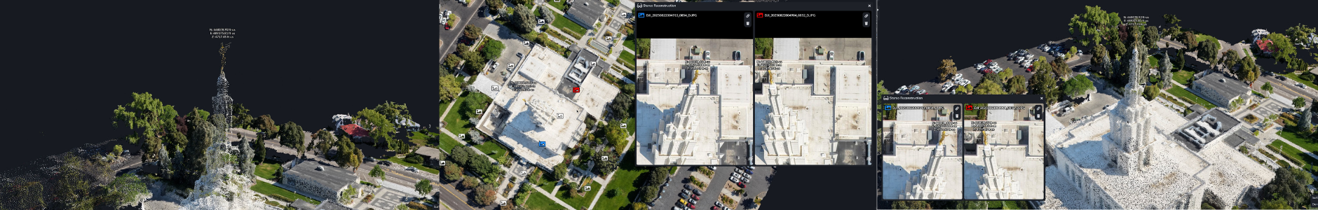
Then, select the Stereo Reconstruction tool button on the left vertical menu to bring up the Stereo Viewer. When you select the image you want to use, assign it to the left or right image to put into the Stereo Reconstruction tool.
Step-by-Step: Assigning Images to Left and Right Viewports
Step 1
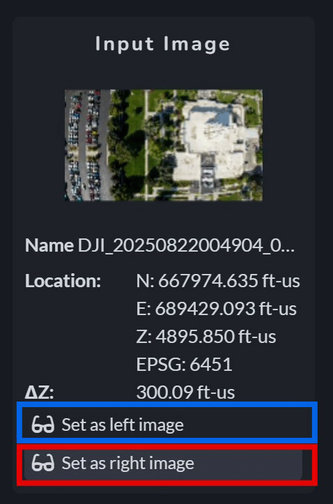
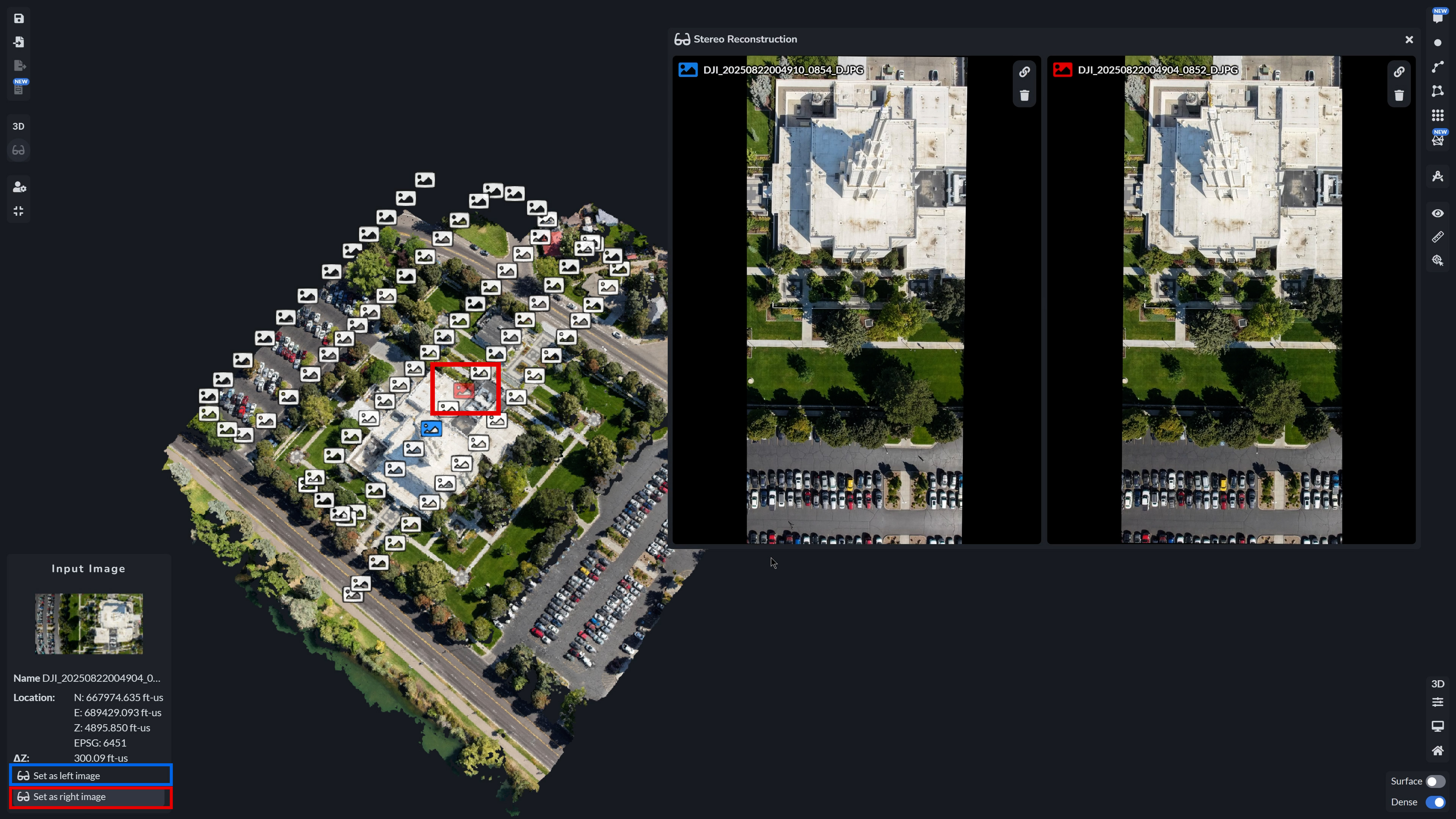
For effective stereo reconstruction, you need to select input images that capture your scene from slightly different perspectives/angles. Start by selecting one of your images and assigning it to either the left or right viewport using the selection panel. Repeat this step for the second image, assigning it to the opposite viewport.
Step 2
By enabling distinct left and right views, the Stereo Reconstruction Tool allows you to observe depth and details that would otherwise be challenging or in some cases, impossible to capture with that specific dataset. This method is especially valuable for projects requiring accurate elevation data or for industries that rely on precise 3D measurements.
Step 3
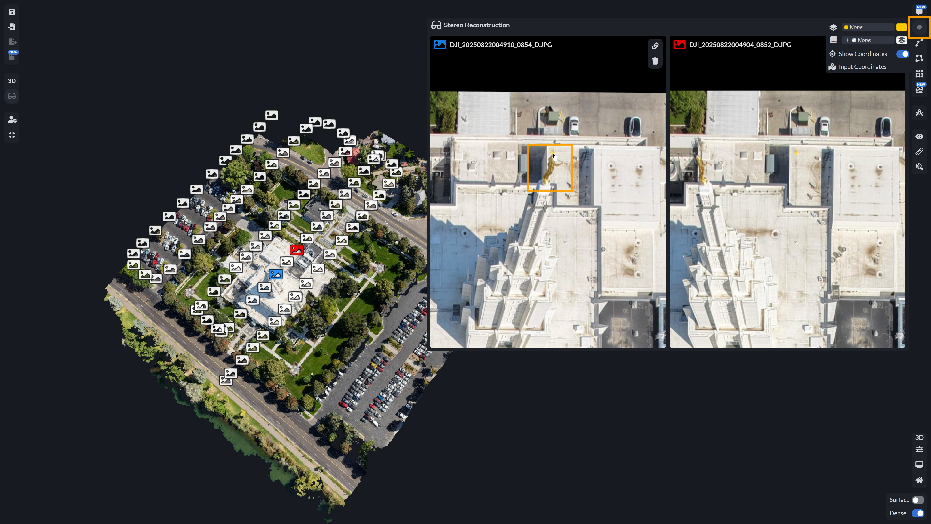
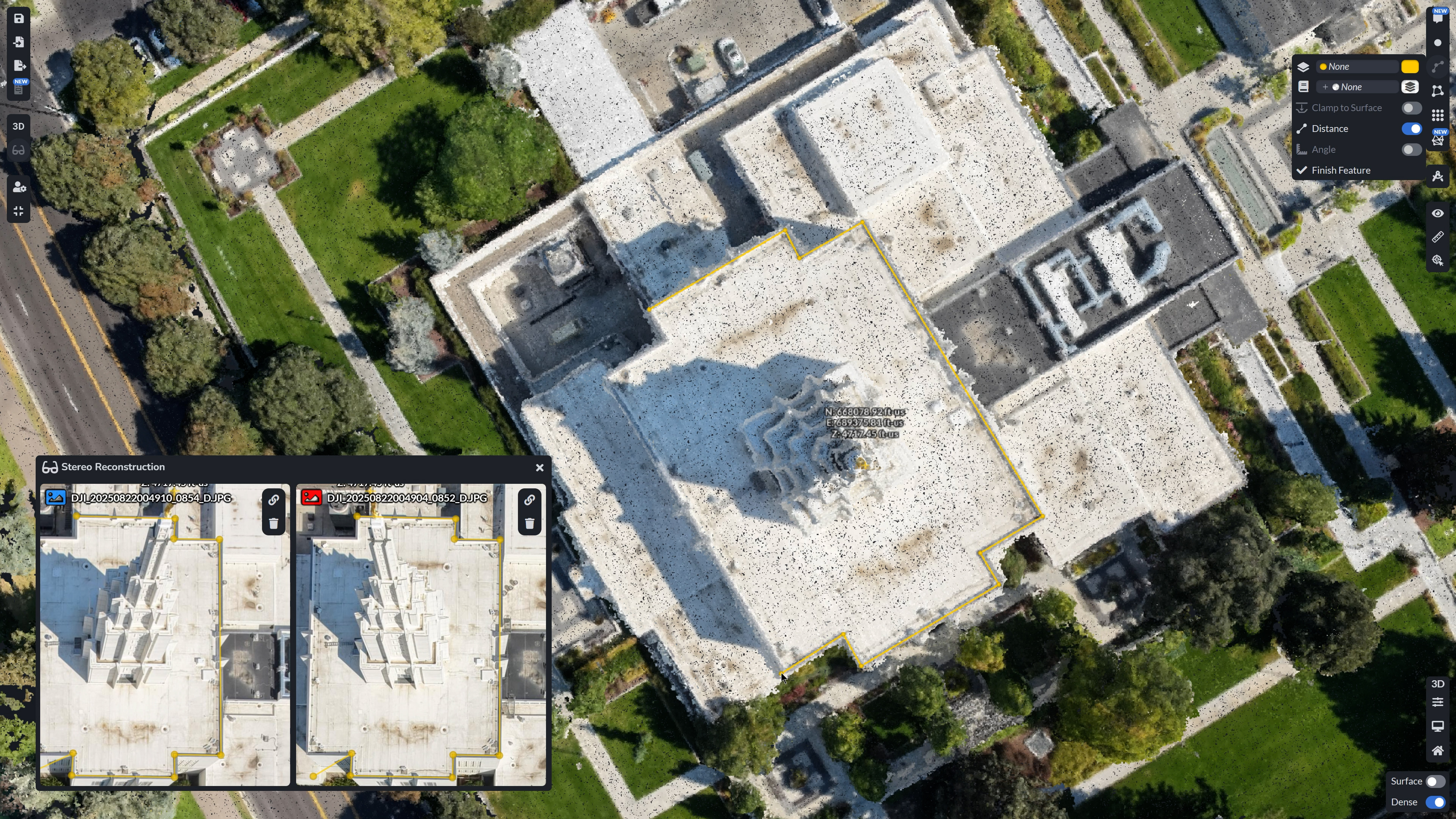
After assigning images to both the left and right viewports, select the Point Tool. Then, click on the location on your 3D Model or Point Cloud where you would like to reconstruct the 3D point – the corresponding point will also appear in the Stereo Reconstruction Tool viewports.
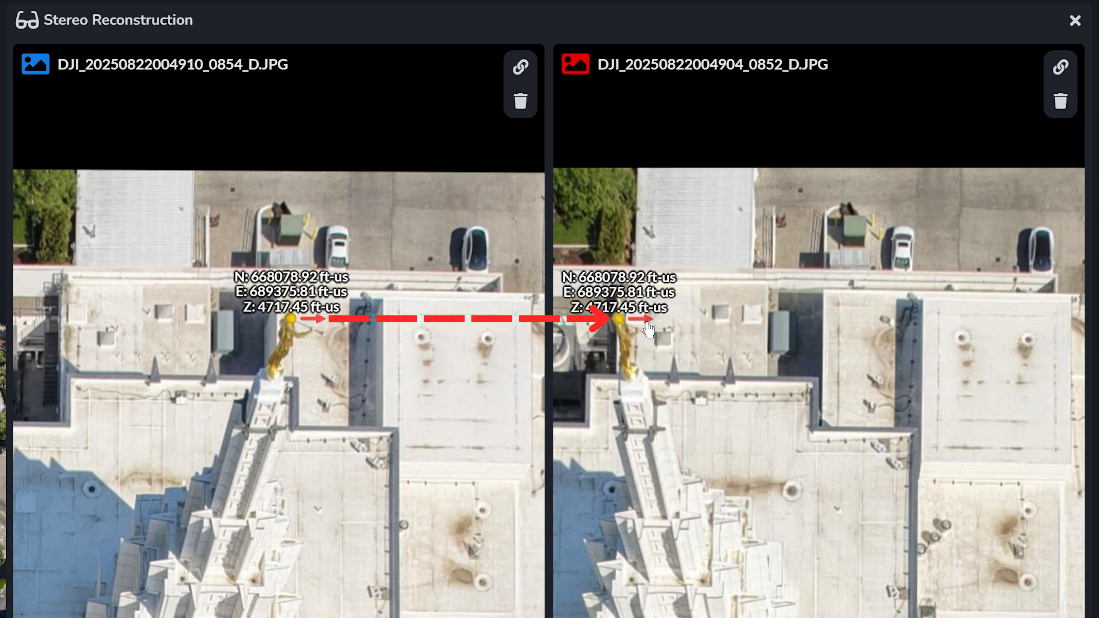
Step 4
Navigate to both viewpoint windows and drag each point to where it should be in the respective photo. As you do this, the point in the 3D model will move to the area where you are assigning, even if that texture was not reconstructed and does not exist in the 3D model.
Using Polygons and Polylines in StereoViewer
In addition to points, you can also use other types of annotations like polylines or polygons. These will appear in the stereo viewer as well, allowing you to trace building edges, mark rooflines, or capture road markings directly from stereo imagery with the same accuracy.
Why Stereo Reconstruction Matters
The Stereo Reconstruction Tool bridges the gap between automated 3D modeling and human-guided inspection. By allowing users to manually assign stereo image pairs and observe depth cues directly, it empowers you to measure and verify critical features that often get overlooked.
While strong results always start with proper data capture, not every dataset is perfect. When sub-optimal or limited imagery crosses your desk, this tool becomes essential. Stereo reconstruction gives you the ability to extract meaningful 3D information even in challenging conditions, offering the control and precision to validate, measure, and refine beyond what automated processing can achieve on its own.