Fixing Distortions with Orthoimage Editing in PixElement
In this article, we will delve into how to edit distorted orthoimages. Please see the corresponding tutorial video below.
🛠 What Causes Ortho Distortions?
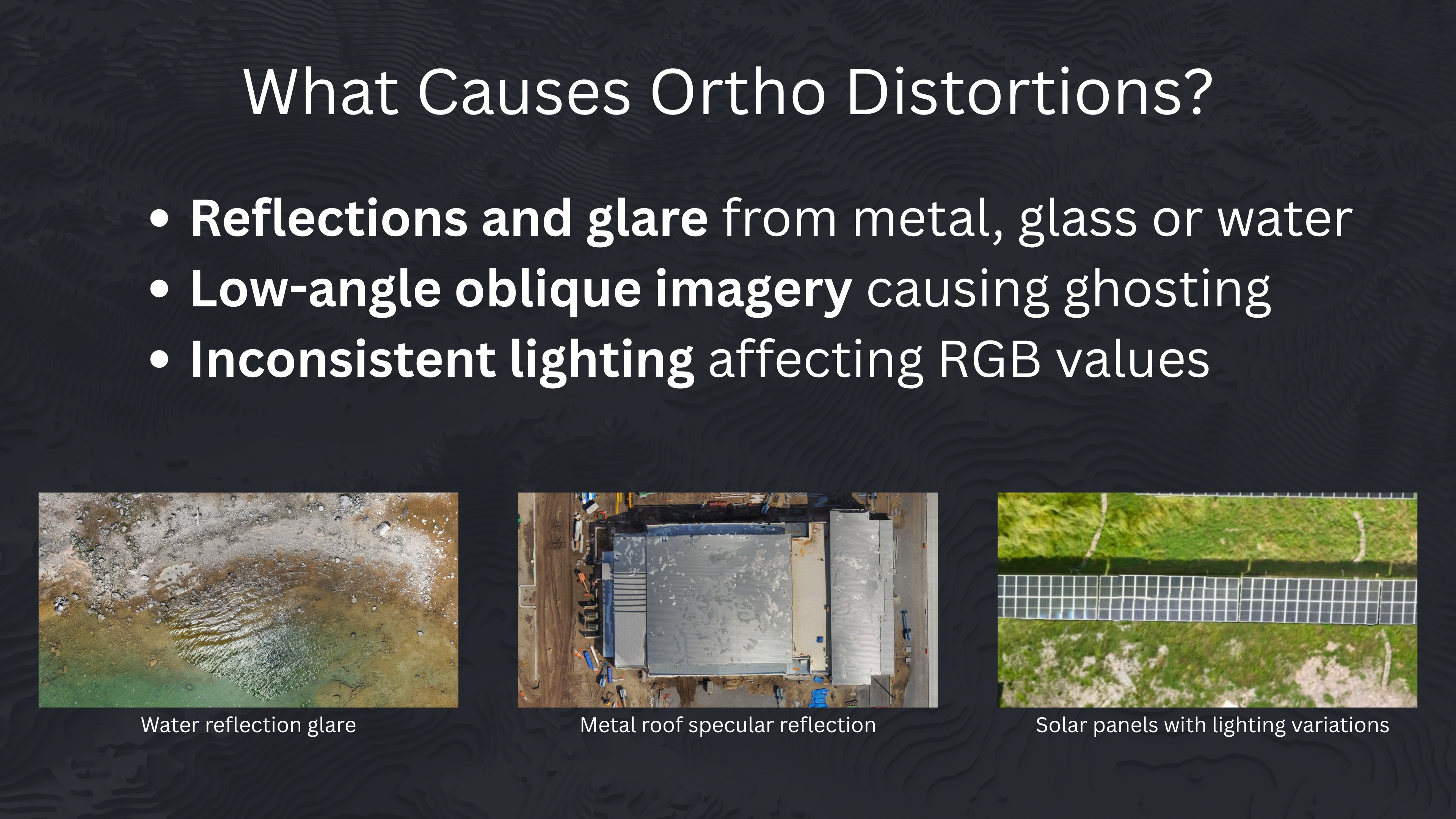
If you’ve ever flown over a metal rooftop or body of water, you might’ve noticed strange streaks, color artifacts, or even missing pixels in your orthophoto. These distortions are typically caused by reflections or glare on shiny surfaces like solar panels, metal barns/industrial roofs, or standing water, having low-angle imagery introducing ghosting or perspective mismatches or inconsistent lighting causing wildly different RGB values across the same surface.
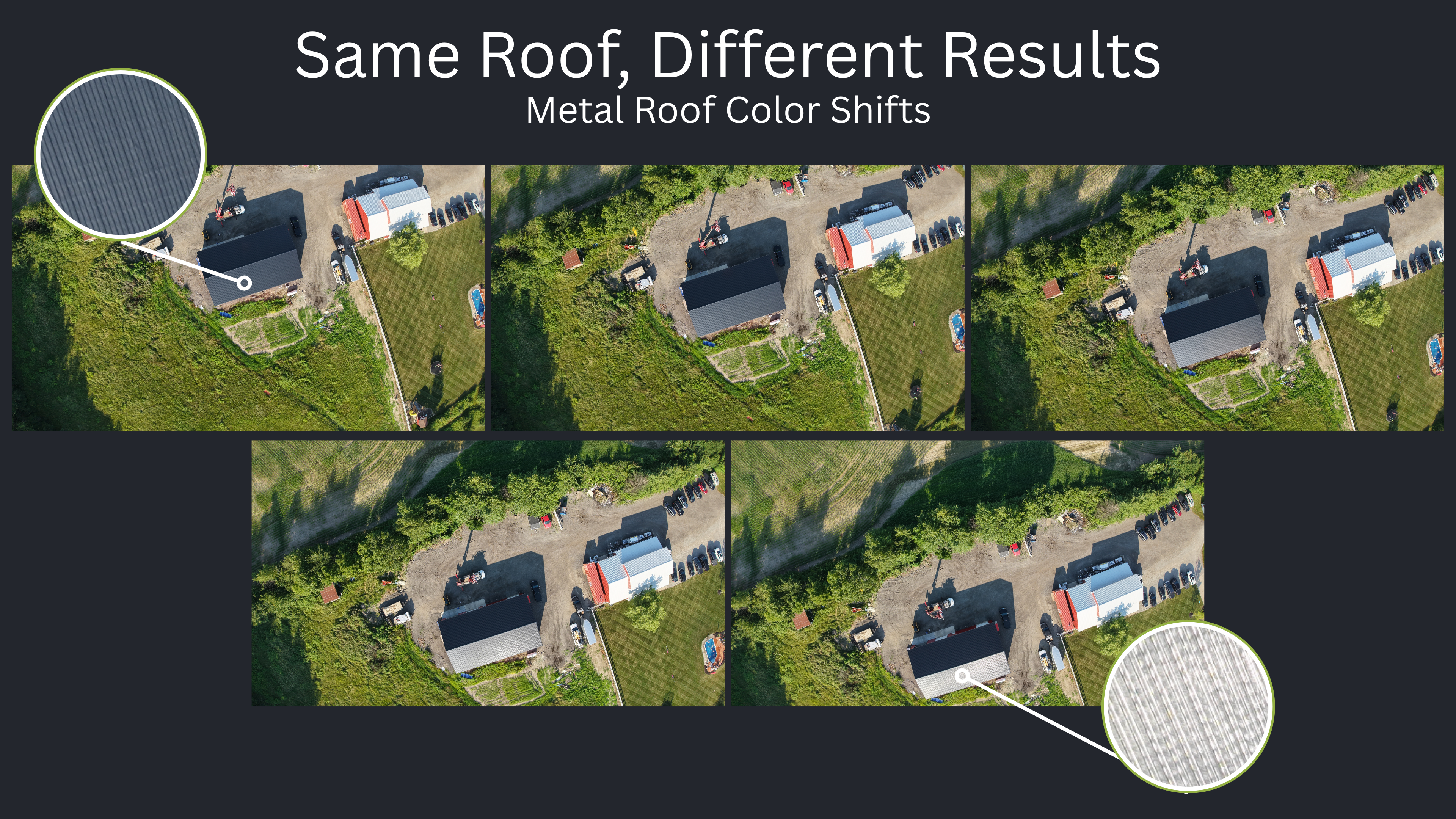
For example, a metal rooftop might appear silver in one photo and bluish-gray or almost white in another, depending on the sun angle and camera view. When these images are stitched together into an orthophoto, the result can look patchy or inconsistent - with visible color seams or tone breaks across a surface that should be uniform.
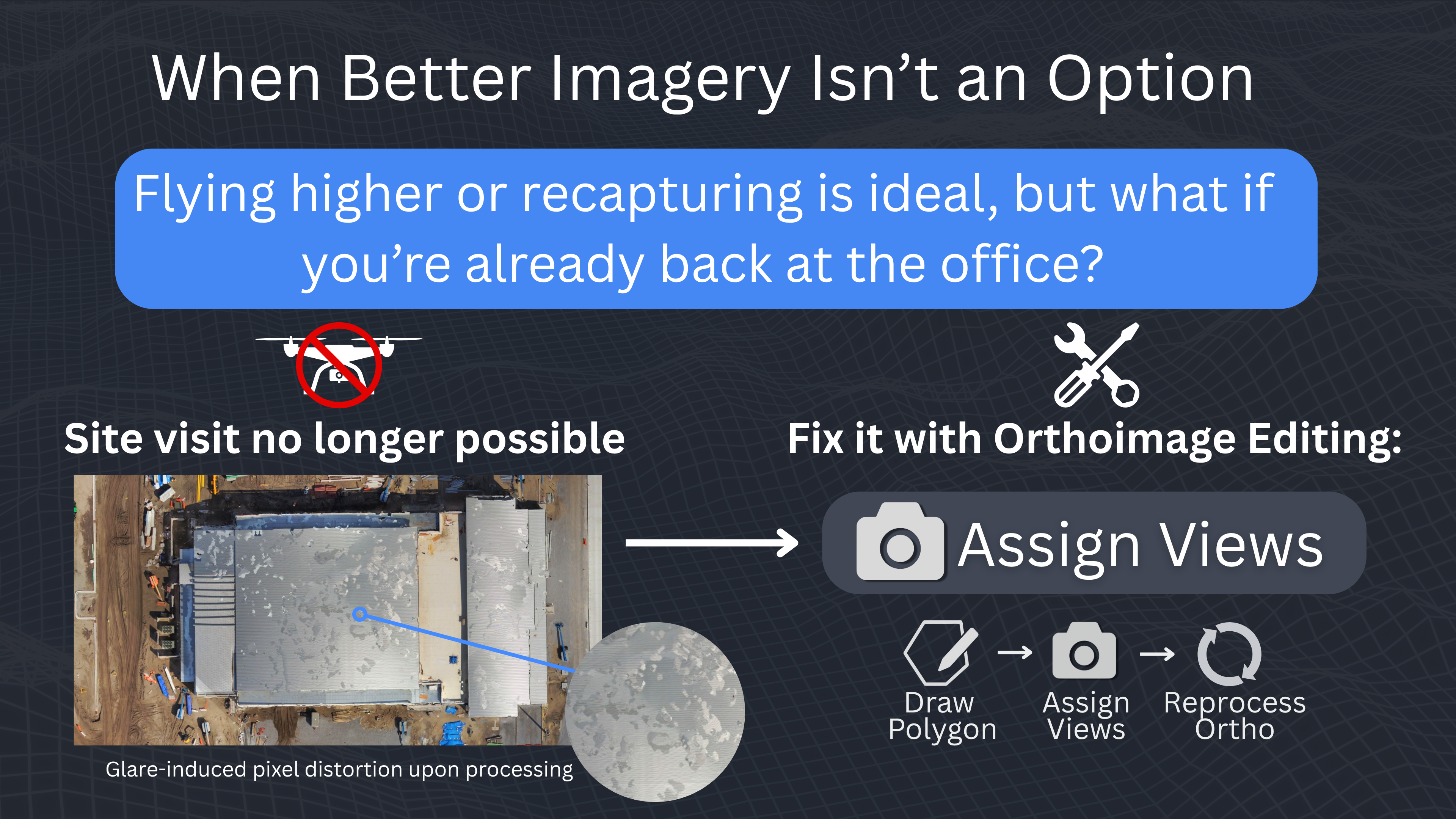
While flying higher or capturing better-quality images can help, that’s not always an option, especially if you’ve already left the site. That’s where the Orthoimage Editing tool can help out. Please note that all orthoediting selections within the canvas should be done in the 2D view mode.
How to Use Orthoimage Editing
Step 1: Identify the Problem Area
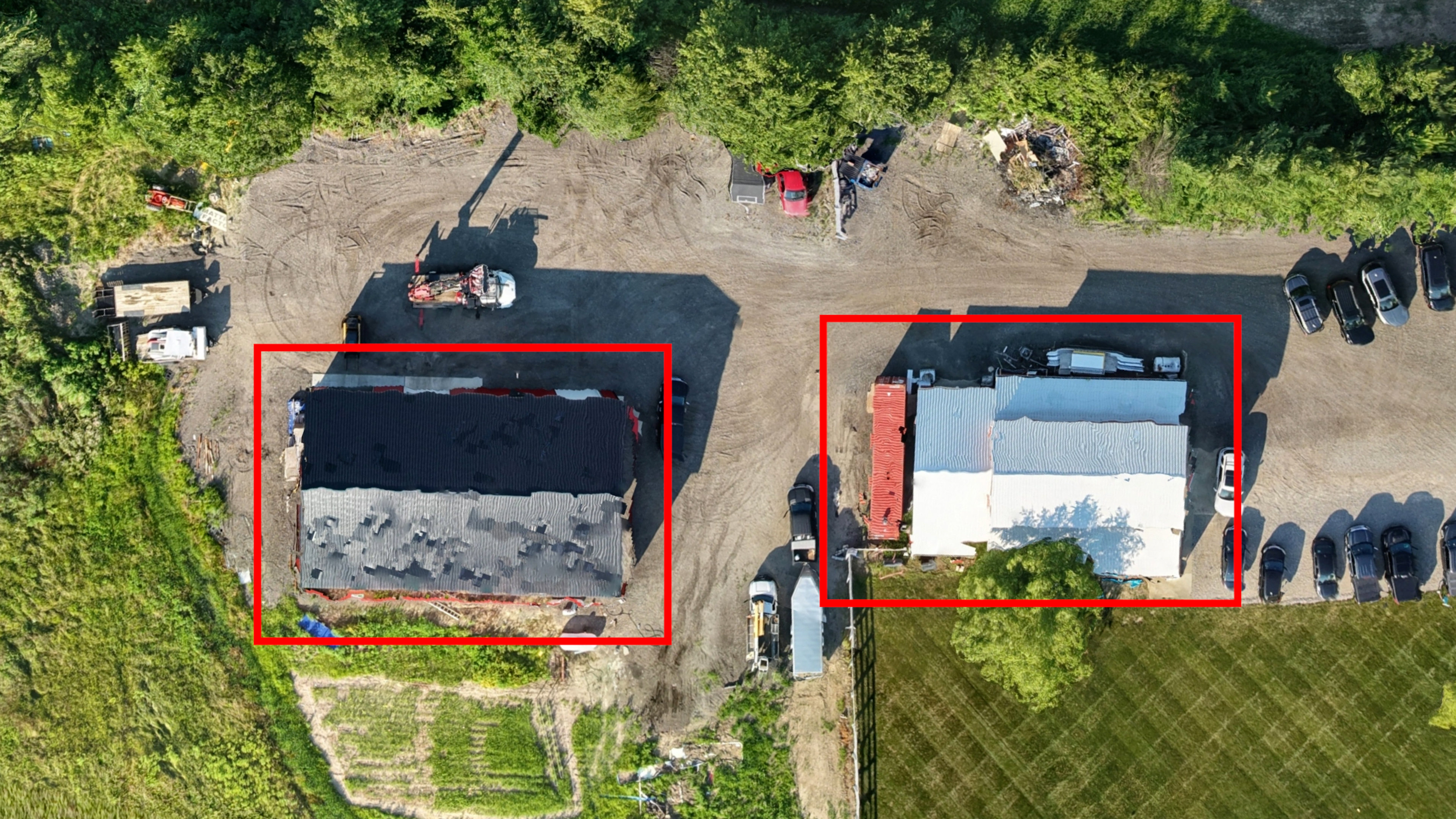
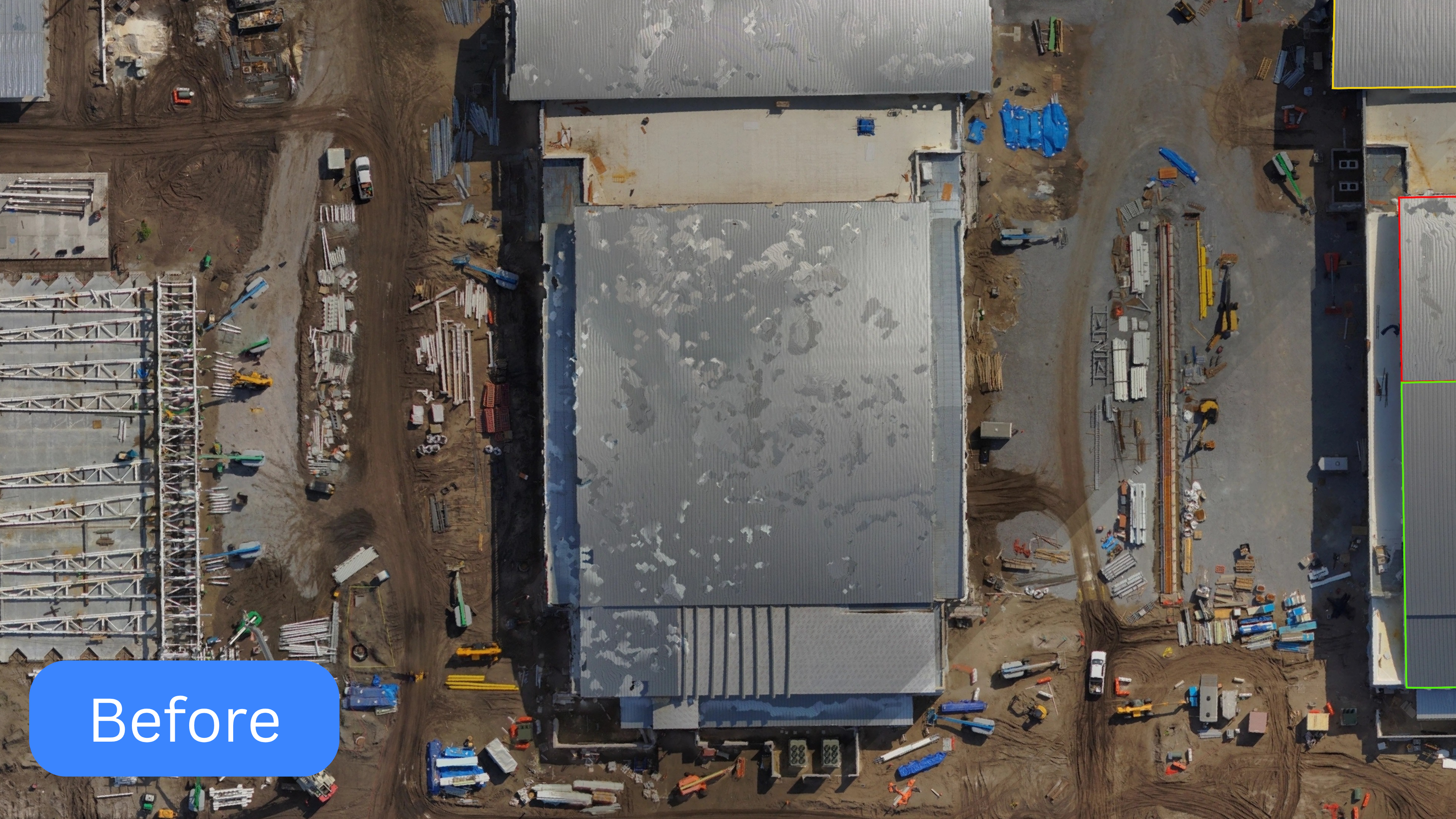
Zoom into the area of your orthophoto where the distortion appears — a metal roof, water feature, or glare-heavy zone.
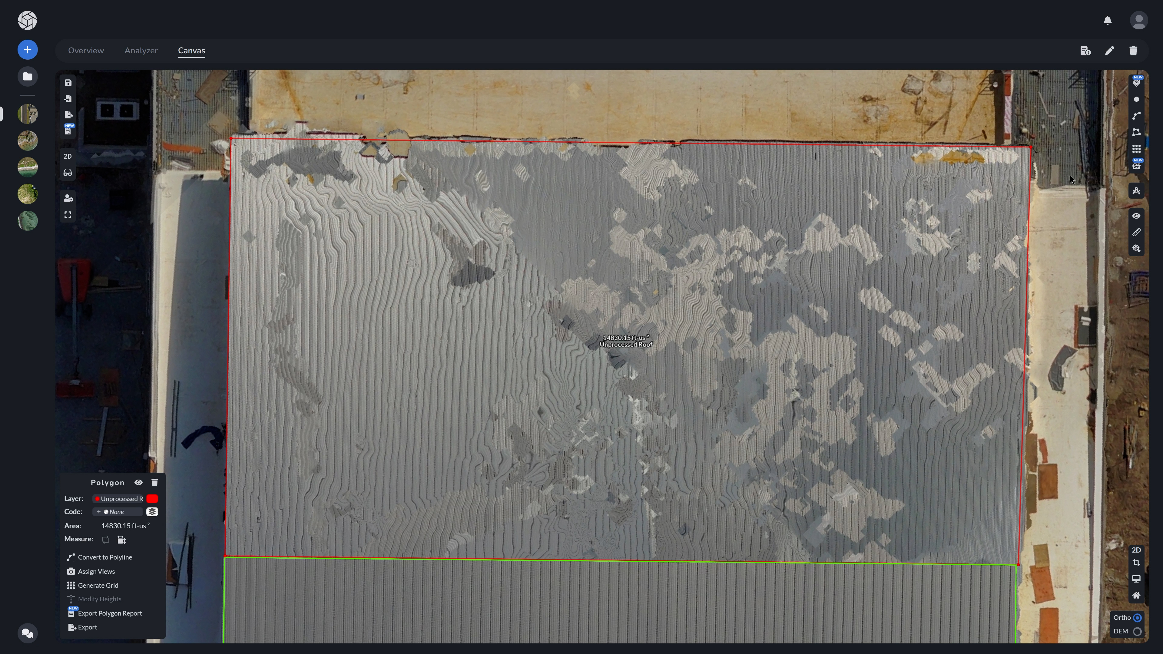
Example: In this case, we are looking at a dataset with multiple metal reflective roofs. Notice the distortion and missing data all over this surface, a perfect candidate for Orthoimage Editing.
Step 2: Draw a Polygon
Using the canvas tools, draw a polygon over the problem area. You can do this for as many problem zones as needed across your dataset.
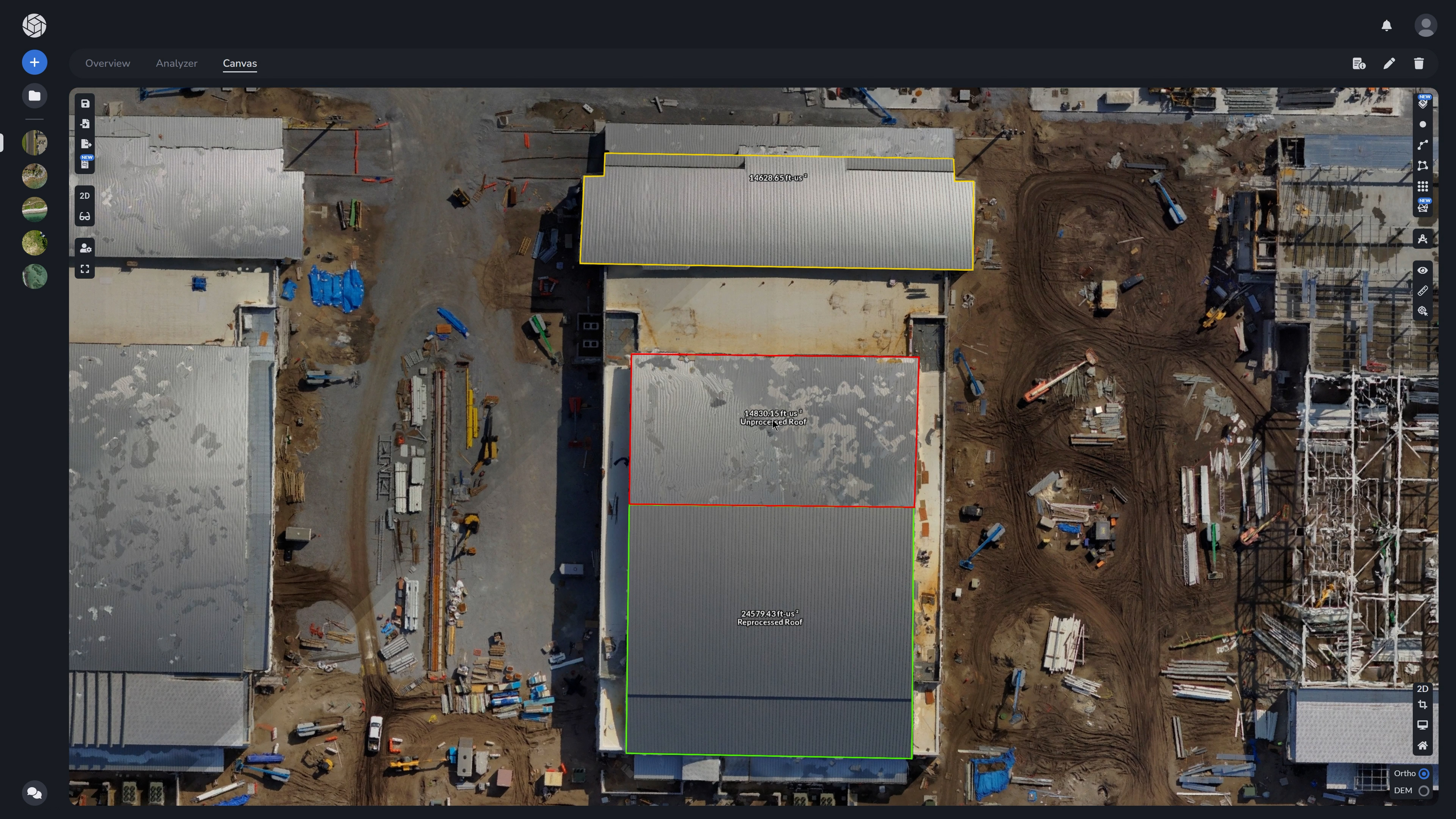
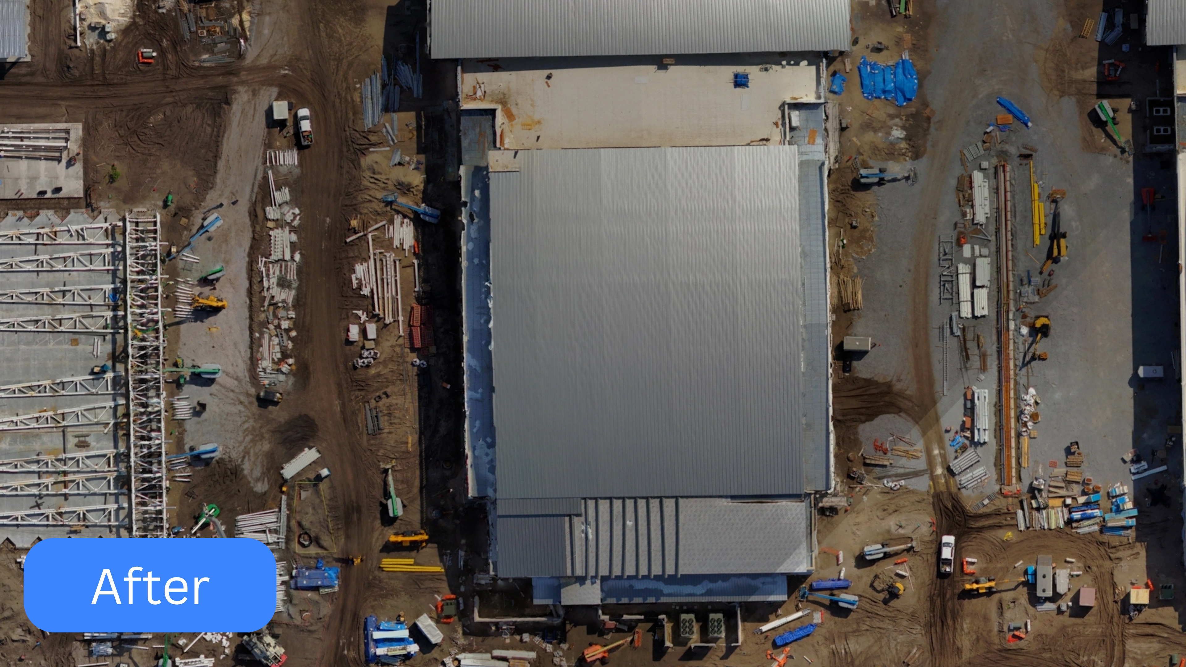
Note, that the metal roof above and below this unprocessed roof have already been corrected and reprocessed. Let’s fix this one up as well.
Step 3: Assign Better Views
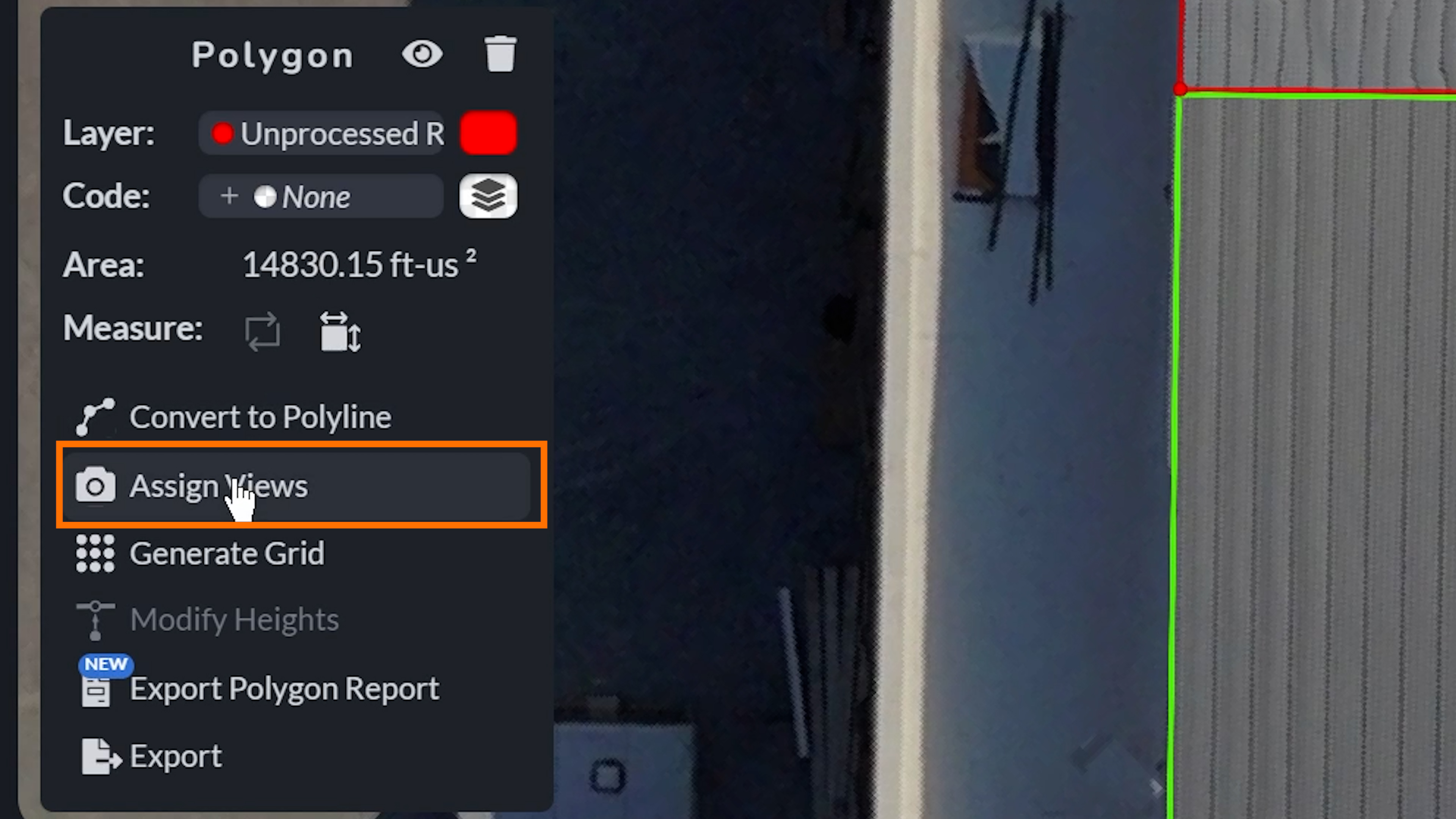
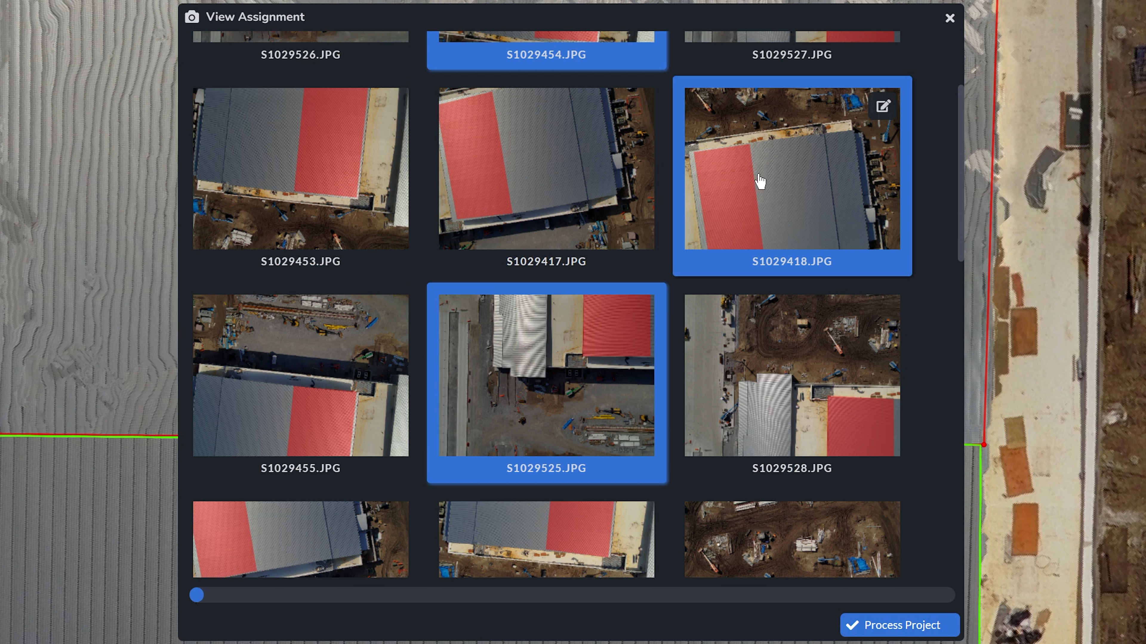
Select your polygon layer and click Assign Views in the submenu. A list of available photo angles will appear, where you should try to choose the clearest, least reflective views. It is recommended that priority should be given to images that have the full polygon area visible in the image, rather than just a segment of it. These will be used to regenerate that section of the ortho.

Step 4: Process the Project
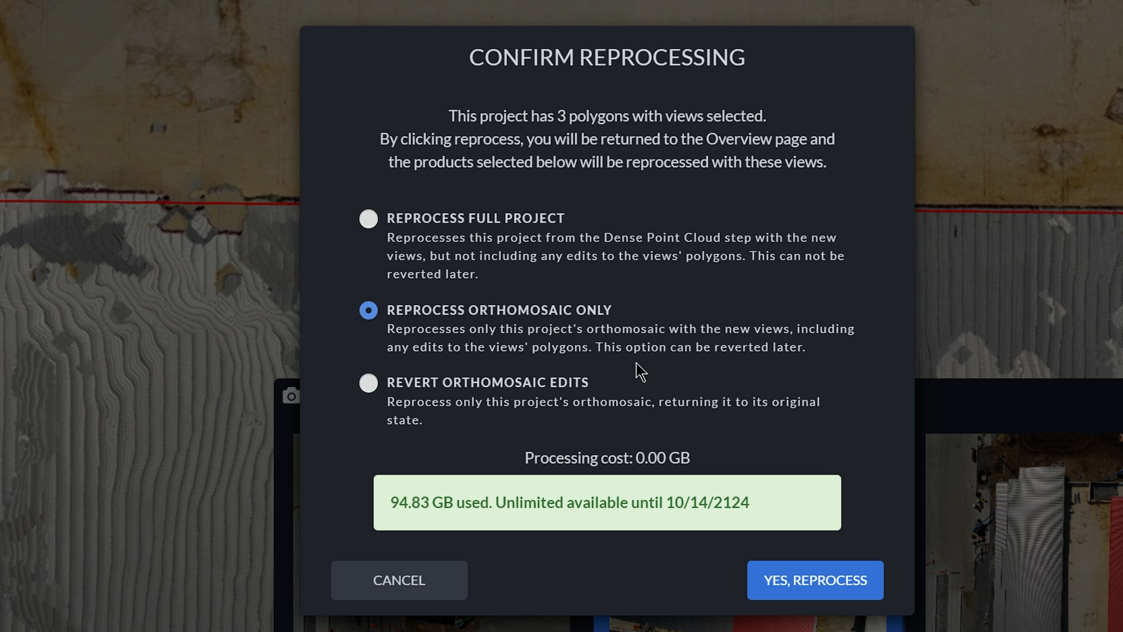
After assigning views to all your polygons, click Process Project. You’ll be prompted with two reprocessing options:
-
Reprocess Full Project – Starts from the Dense Point Cloud step using your selected views, ideal if the mesh also needs refinement.
-
Reprocess Orthomosaic Only – Regenerates the ortho from your assigned views, skipping 3D processing entirely.
-
Revert Orthomosaic Edits - Returns the orthomosaic to its original state. This tool only appears if you have already reprocessed orthoimages in the past in the same project.
Choose the option that best suits your situation, then confirm with Yes, Reprocess to begin.
When to Use This Tool
Orthoimage Editing is especially useful when:
-
You can’t return to the field for a re-shoot
-
Your ortho needs to meet higher visual standards for client reports
-
You’re trying to fix minor defects without reprocessing the entire dataset
Conclusion
With Orthoimage Editing, you no longer have to settle for distorted imagery. Whether you’re dealing with reflective surfaces, lighting inconsistencies, or just need a touch-up before delivery, just draw, assign, and reprocess. Simple, precise, and built for real-world mapping.